Busbar Systems in Switchgear: The Complete Engineering Guide
A busbar is a rigid, flat conductor used to transport high electrical current inside switchgear. It’s kind of like a power highway, receiving electricity from an incoming source and then distributing it efficiently to multiple circuits. In switchgear, the material cost of the busbar system can account for around 30% of the total. It also strongly affects temperature rise, short-circuit withstand, cabinet layout, and manufacturing complexity. Yet busbars are often treated as an afterthought—just “big pieces of copper” inside a panel. In reality, the design of busbars is one of the most critical engineering decisions in switchgear architecture.
A welldesigned busbar system provides safe, efficient, and reliable power distribution, whereas a badly designed one can lead to catastrophic results such as overheating, short-circuit failures, and costly downtime.
This blog provides a complete, practically grounded understanding of busbar systems.
Functions of Busbars?
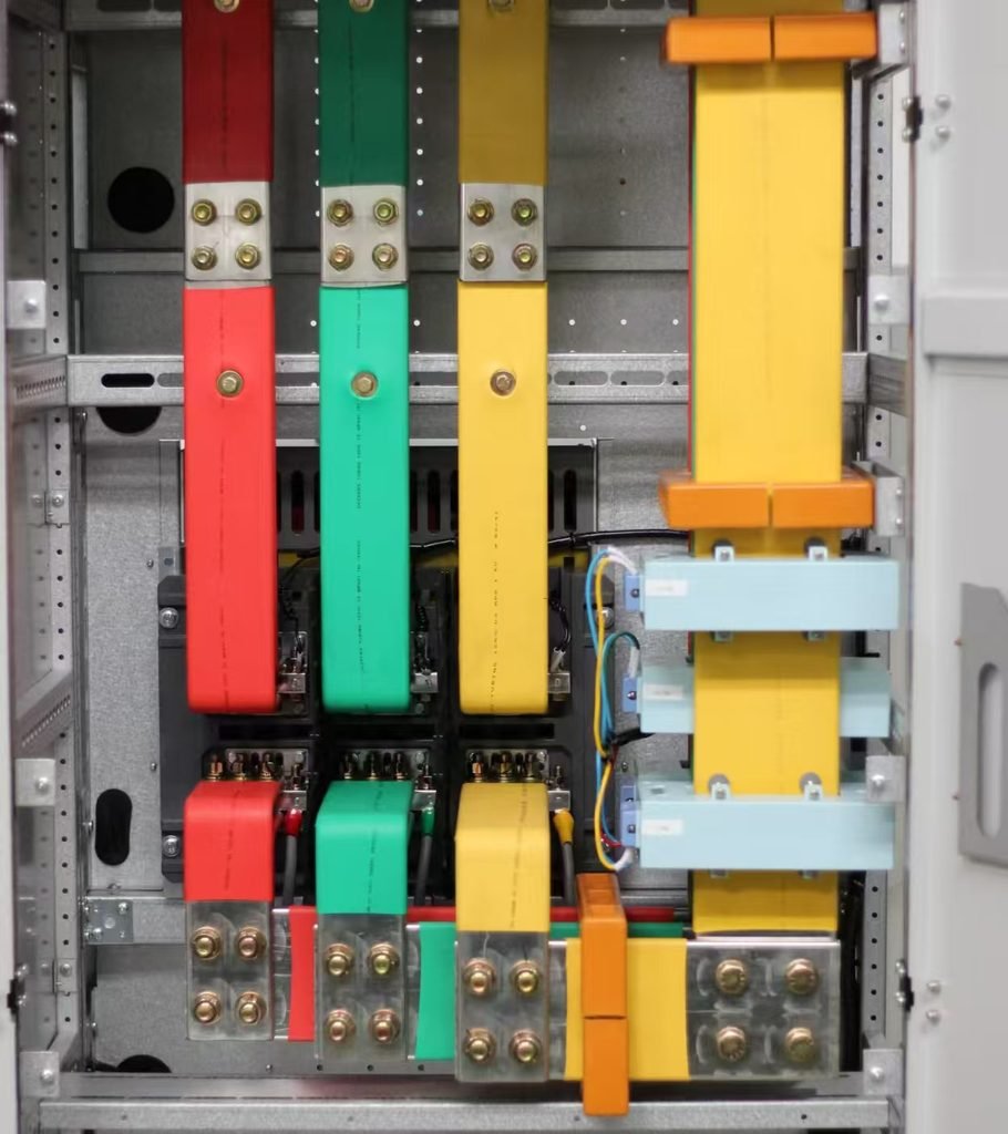
- Conducting Electricity Efficiently: Busbars are low-impedance conductors that permit current to flow between various electrical components.
- Simplifying Power Distribution: Power connections are combined through busbars, instead of dozens of individual wires running to each electrical component.
- Improving System Safety: The fixed and predictable shape keeps phases properly spaced and organized, which helps reduce the risk of accidental contact, overheating, and short circuits.
- Allowing for Scalability: The engineer can expand the power systems by adding new branches to the existing busbar system to meet actual needs.
Busbar Materials: Copper vs. Aluminum
The choice of materials is of first importance for conductivity, weight, reliability of joints, and endurance of faults.
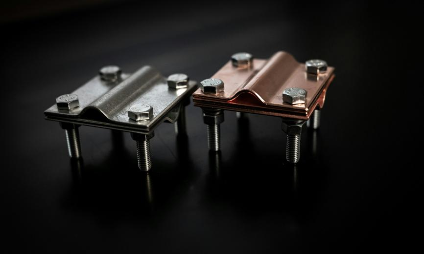
Copper Busbars
Conductivity: ≥97% IACS (International Annealed Copper Standard)
Advantages: Higher conductivity, excellent mechanical strength, superior corrosion resistance, smaller cross-sections for the same current capacity.
Application scenarios: Critical systems where performance is critical.
Aluminum Busbars
Conductivity: Approximately 61% IACS (per GB/T 5585.1-2018)
Advantages: 30–50% lighter than copper, much lower material cost.
Disadvantages: lower conductivity than copper, more prone to oxidize.
Application scenarios: Residential and small commercial installations.
Surface Treatments of Busbars
Bare copper and aluminum will inevitably oxidize when exposed to air, which will increase surface resistance and operating temperature at joints. Proper surface treatment is therefore essential for long-term reliability and safety.
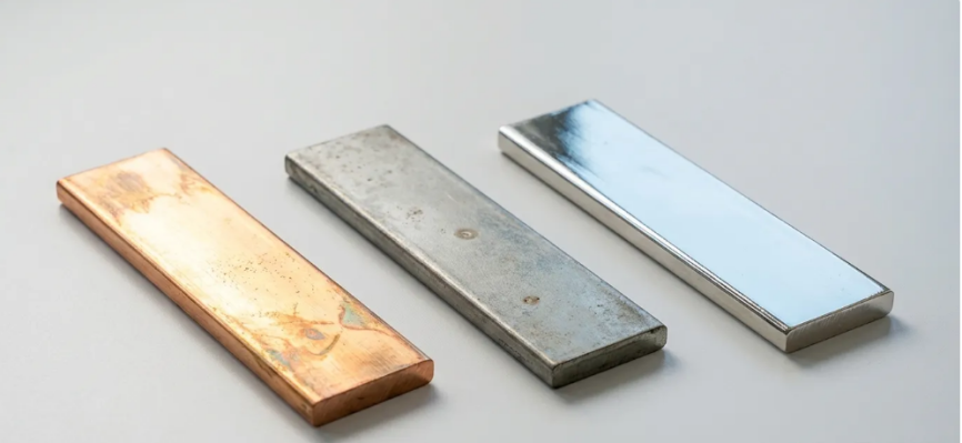
Tin Plating
Tin plating provides good oxidation resistance at a reasonable cost and provides a stable contact resistance over the life of a bolted joint. Tin-plated busbars are reliable in typical commercial and industrial environments.
Silver Plating
Silver Plating offers the lowest contact resistance of any common finish. It is the choice for high-current junctions, critical bolted joints, and where maximum reliability is required. The only drawback is the high cost.
Nickel Plating
Nickel plating provides an excellent level of resistance to corrosion and oxidation. It is suitable for environments subject to industrial corrosion or mechanical wear.
Common Shapes and Configurations
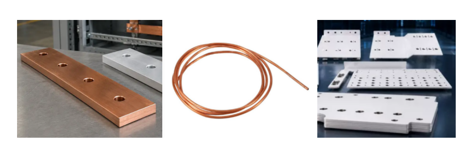
The cross-sectional shape of a busbar is not merely a matter of manufacturing preference. It directly influences the current density, the heat dissipation surface, the mechanical rigidity, and the way the conductor fits inside the cabinet.
Flat rectangular busbars are the most common in switchgear. They have a large surface area and are easy to mount. Thickness usually ranges from 5 mm to 12 mm, and the width is chosen to meet the required current rating within the available phase spacing.
Tubular busbars are hollow and lighter, assisting in the cooling of high current systems.
Laminated busbars are made from multiple thin conductive layers, separated by thin insulation material. They can save space and reduce current loss.
Types of Busbars in Switchgear
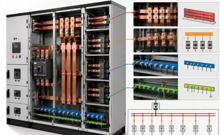
A switchgear busbar system is not only a big hunk of copper or aluminum. It is a carefully engineered network of conductors: main busbars, distribution busbars, feeder take-off bars, neutral busbars, and protective-earth (PE) busbars, each of which performs a specific task in its position.
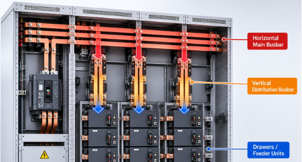
Main busbars form the main power-distribution path through the switchgear. They are often run horizontally through several sections, fed by the incoming breaker and then distributing power to outgoing feeders, motor-control sections, or another busbar section. The current on the main busbar is not the same everywhere. Near the incomer, it may carry the combined current of all feeders but decrease after each feeder tap. Standardized systems usually have the same busbar sizes for all sections, though, to simplify manufacturing, spare parts, and future expansion.
Distribution busbars act as the bridge between the main busbars and individual functional units, channeling power to each unit. They are particularly important in motor control centers (MCCs) and withdrawable switchgear, where numerous outgoing units all need to draw from a single shared supply.
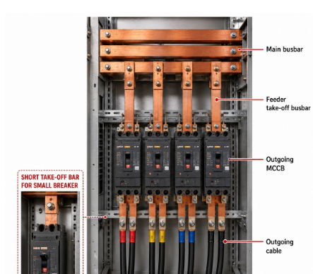
Feeder take-off busbars carry current from the main or distribution busbars to individual outgoing devices. A small breaker may use short take-off bars; a large breaker may require several bars in parallel per phase.
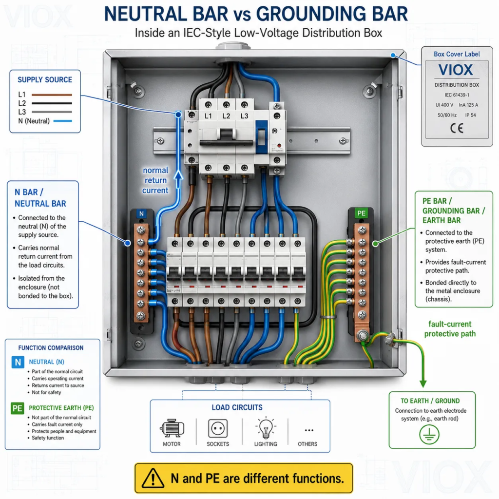
Neutral busbars should never be automatically treated as reduced versions of the phase busbars. The size of neutral busbars depends entirely on the electrical system and connected load types.
PE busbars play an entirely different role, unlike phase and neutral conductors. They form a dependable path for fault current and ensure that all exposed conductive parts of the switchgear to the same electrical potential. They carry no continuous current during normal operations.
Parallel Busbar Arrangements & Current Sharing
High-current switchgear often uses two or more parallel conductors per phase to increase the total conductive cross-section area and the heat dissipation surface area. However, four bars in parallel are not automatically equivalent to a single solid conductor with the same total area. Current sharing is affected by many factors such as spacing between bars, magnetic fields from adjacent phases, the length of the bar, etc.
Electrical & Thermal Design
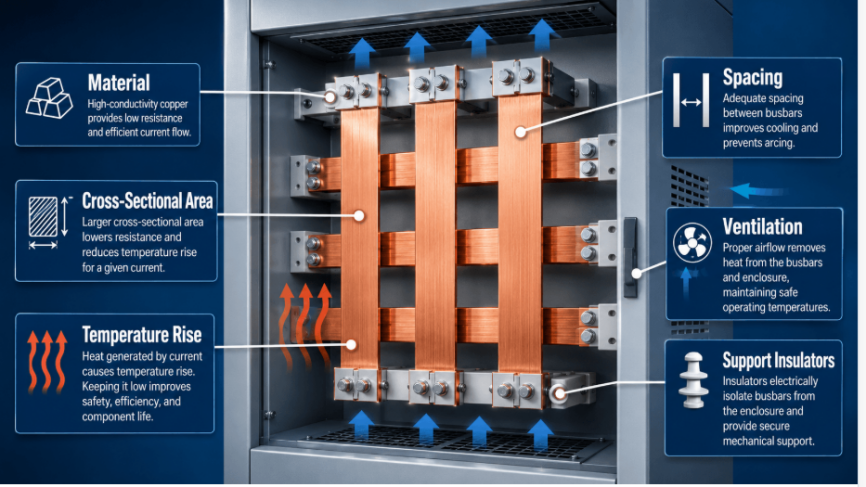
The hidden challenge in busbar design lies in how to manage the heat produced during this process. Whenever electricity flows, the conductor warms up; the effect is strongest at bolted joints. A flat, wide busbar exposes far more surface area to the surrounding air than a round one of equal volume, letting heat escape faster. When passive cooling—relying on natural airflow through carefully designed spacing and layout—proves insufficient, engineers may add fans to the assembly. Finally, they would validate each design through a thermal operational test.
Short-Circuit & Mechanical Design
Busbars must stay mechanically steady all the time, especially during fault events. A solid structure can avoid damage, loosening, and overheating. Peak fault current generates strong magnetic repulsion or attraction between phases, which can cause some conductors to bend or, in some cases, get dislodged. Therefore, mechanical design really has to consider busbar spacing, insulating materials, and mechanical supports, as well as mechanical stress, vibration, and thermal expansion that occur during normal operation.
Manufacturing & Quality Control
Joints are basically the weakest link in a busbar system. Bolted connections demand controlled torque: too little torque causes high contact resistance and hot spots; too much damages the bar or the insulator. During manufacturing, precise cutting, bending, and forming help to preserve mechanical integrity. Quality checks should confirm torque, alignment, and spacing. In addition, infrared thermography can reveal overheating joints fast enough to prevent faults in time.
Frequently Asked Questions (FAQ)
Need switchgear for your next project? Explore our switchgear solutions or contact our engineering team for a technical consultation.